

Статьи
Инструкции по разбору MacBook Pro 15 (1 часть)
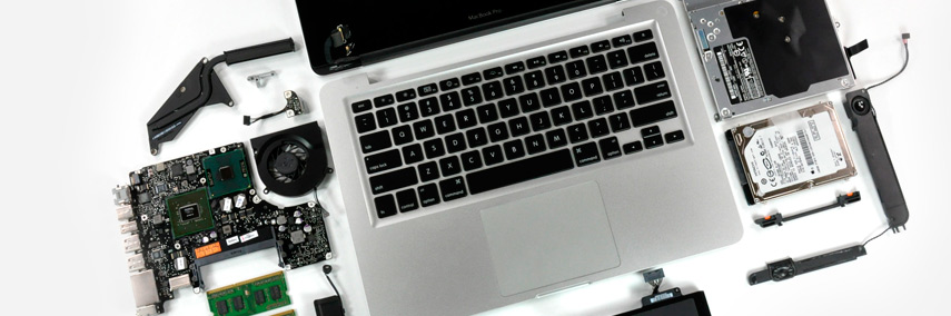
MacBook Pro (15-inch Core 2 Duo)
General Information
Product View

Overview
The MacBook Pro (15-inch Core 2 Duo) is the next generation of Intel-based MacBook Pro
professional notebooks. As the name implies, it is based upon the new Intel Core 2 Duo chip,
increasing processor speeds to 2.33GHz.
On the exterior, the MacBook Pro (15-inch Core 2 Duo) difers from its predecessor in two ways.
The LED for the iSight camera no longer depends an opening in the display bezel to be visible.
And more signifcantly, the reintroduction of FireWire 800 adds a new port to the right side of the
bottom case, increasing the ports from four to fve.
A new MagSafe Airline Adapter is now available for both the MacBook Pro and the MacBook. Plug
the MagSafe Airline Adapter into the EmPower port nearest your airline seat. Some airlines may
have 20 mm in-seat ports that require the use of an additional adapter (included in the kit).
Main service and feature differences from previous models:
- Intel Core 2 Duo microprocessor architecture: 2.33GHz and a 2.16GHz option
- Up to 3GB DDR2 memory now supported
- 120GB 5400 RPM hard drive standard
- 100GB 7200 RPM hard drive optional
- 200GB 4200 RPM hard drive optional
- FireWire 800 port
- 6x SuperDrive with dual-layer burning support
- New trackpad-enabled zooming feature
New Parts and Procedures
Main Logic Board
The MacBook Pro (15-inch Core 2 Duo) not only hosts the Intel Core 2 Duo microprocessor chip,
but it also reincorporates the popular 9-pin FireWire 800 port from the PowerBook series. Note
that the additional port makes this bottom case incompatible with previous the MacBook Pro.

Like the MacBook, the MacBook Pro (Core 2 Duo) now utilizes JST wire bundle connectors that
disengage by lifting up and pulling the connector out of its mating part on the logic board. Just
snap the connector back in. The fans, thermal sensors, and back battery all use this connector.

As with its predecessor, the composite and S-video connection is still available using the optional
Apple DVI to Video adapter. The microprocessor is soldered to the main logic board. It is not
upgradable.
Memory
The maximum supported amount of memory is 3 GB. While you will have a perfectly bootable
system with two (2) 2GB RAM modules installed—and even About This Mac will report 4GB of
installed memory—the system will only be able to address 3GB of that installed RAM.
AirPort Extreme
The AirPort Extreme card is a new design that utilizes a three-wire antenna solution. A color-
coded label will identify which wires go to which terminals on the card.

Bluetooth
The Bluetooth module and antenna have been moved from the bottom case near the hard drive
to a position underneath the top case.
iSight Camera Status LED
The opening for the green status LED to the right of the camera no longer appears in the display
bezel. When the LED lights up, it is now visible through a clever pattern of micro perforations.

Keyboard
The keyboard backlighting has been improved. In addition, the programming of the caps lock
key was changed to fx a developer keyboard mapping issue. Thus, this keyboard cannot be used
in previous MacBook Pro 15-inch systems. The caps lock key will not be recognized.
Right Speaker Assembly
The right speaker is now one single part. In the previous design, a speaker housing was mounted
below the main logic board and the right speaker driver was mounted through the main logic
board into the housing with its wire running over the top of the main logic board.
The new single piece design has the entire right speaker installed frst with the main logic board
placed over it. This design does require the entire main logic board to be removed to change the
right speaker. In addition, the right speaker wire now runs below the main logic board, under the
heat sink along back vent wall.
Trackpad
The trackpad now supports screen zooming, much like the keyboard-based Zoom feature in the
Universal Access System Preference pane. When holding down a user-selectable modifer key (in
the Keyboard & Mouse System Preference pane), gesturing with a forward fnger motion on the
trackpad will cause the image on the screen to zoom in. The reverse motion will zoom out.

There are three users options that adjust how the customer can move within a zoomed screen
and how smooth the image will look.

Hard Drive
The hard drive comes with a metal disk attached to its top cover to dampen hard drive noise. This
disk is not removeable. The replacement drive will come with this dampener pre-installed.
Temperature Concerns
The customer may perceive this system to run hotter than previous models. However, the normal
operating temperature is well within national and international safety standards. Still, customers
may be concerned about the heat generated by their machine. To prevent an unnecessary repair,
you can compare a customer’s computer to a running model, if available, at your repair site.
For more information on temperature concerns and customer perception, refer to Knowledge
Base article 30612: Apple Notebooks: Operating Temperature.
Display Takeapart
With the MacBook Pro (15-inch Core 2 Duo), we have brought back the whole display clamshell
as a service part. However, unlike the 17-inch Core 2 Duo, we offers some parts which are
accessible by the removal of the display rear housing.
Specifically, a Service Provider can replace:
• Display hooks
• Inverter
• Display housing
• Sleep magnet
All other parts including the LVDS cable are serviced with the whole clamshell module.
Identifying the MacBook Pro (15-inch Core 2 Duo)
Below are views of the MacBook Pro (15-inch Core 2 Duo), with identifying features.
Left side: MagSafe™ magnetic power connector.

Right side: New FireWire 800 port.

Front: Infrared sensor window.

Rear: Wider venting than previous MacBook Pro.

Display bezel: MacBook Pro.

Serial Number and Ethernet ID
The Serial Number and Ethernet ID are located in the battery bay.

Tools
The takeapart procedure for the MacBook Pro (15-inch Core 2 Duo) requires the following tool
- Clean non-marring work surface
- ESD wrist strap and mat
- Multi-compartment screw tray (such as a plastic ice cube tray)
- #0 Phillips screwdriver (magnetized)
- #1 Phillips screwdriver (magnetized)
- Torx T6 screwdriver (magnetized)
- 4 mm socket wrench
- Black stick (nylon probe 922-5065) or other non-conductive nylon or plastic fat-blade too
- Razor knife
- Needle-point metal probe
- Needlenose pliers
- Tweezers
- Kapton tape (922-1731) (0.5-inch x 12-yard roll)
- Thermal grease (922-7144)
- Gasket kit (076-1238)
- Alcohol pads
- Fine-point felt-tip permanent marker
- Apple Pro keyboard and mouse (for troubleshooting)
Electrostatic Discharge (ESD)
Use a properly grounded ESD wrist strap and mat when working on the inside of the computer.
Service Manual Note
In this manual, graphics or photos are intended to help illustrate procedures or information only,
and may show diferent levels of disassembly, board colors, confgurations, or computer models,
than your computer.
Kapton® Tape Note
Kapton tape is used to secure cables and connectors where necessary.
During disassembly, note any Kapton tape use and locations—reapply in the same manner. Do
not over apply or build up tape on top of old tape; space tolerances are tight and build up or
extraneous use of tape may cause pressure on other components.
Cable Routing Note
The MacBook Pro matches the same one-inch enclosure height established with the PowerBook
G4 17-inch series of systems. More so than ever, the placement of parts and wiring is critical.
During disassembly, note cable routing. Reassemble in the same manner. Verify that cables do
not route over components when they should route into lower positions or channels. Verify that
the cables are not strained or applying pressure onto other components.
Screw Measurement Note
All screw measurements given are the specifed full length. Actual measured lengths may vary.
Foot
Tools
This procedure requires the following tools:
- Foot kit
- Tweezers or needlenose pliers
- Soft cloth
Preliminary Step
Before you begin, check the foot location that needs replacement and verify that the case plug is
attached. Also verify that the case plug, and the case foot in the kit, match the pictures below.

Procedure
Warning: The glue used in this procedure can bond instantly to skin. Do not touch the glue.
In the event of contact, review the safety instructions at the end of this document. For
additional information, refer to the glue manufacturer:
Elmer’s Products, Inc.
Columbus, OH. 43215-3799
www.krazyglue.com
1.Place the computer upside down on a clean, lint-free cloth or other nonabrasive surface.
2.Select a foot from the kit. Verify that the case plug and case foot match (refer to the images
shown in the table). Do not use a foot that does not match.
3.Make sure the plug area on the bottom case is clean. If any portion of the soft rubber foot
remains, remove it so that only the hard plastic plug is visible.
Important: When positioning the foot, make sure the indents and bumps of the rubber foot
match up and ft into the corresponding indents and bumps in the plug. This ensures a
balanced and level ftting. (Note: The picture below may be a diferent foot than on the
computer, and is for illustration only.)

4. Warning: GLUE IS AN EYE AND SKIN IRRITANT. BONDS SKIN INSTANTLY. Do not touch the
glue at any time. Before opening the glue, review the safety instructions at the end of
this document.
Important: The glue tube included in the kit is sealed until frst use. Do not break the seal
until you are ready to use the glue. To break the seal, hold the tube upright and away from
you. Place the hollow nozzle cap on the tube and tighten it all the way down. The tube is
then ready to dispense the glue through the nozzle cap.

5.Apply one drop of glue to the plug on the bottom case. Do not spread the glue.
6.Using tweezers or needlenose pliers, carefully position the new foot so its textured surface
fts into the inner ring of the plug.
7.Using the end of the tweezers or pliers—not your fnger—lightly press and hold the foot in
place for 30 seconds.

2.Before turning over the computer, allow the glue to set for at least 15 minutes.
3.Discard the tube of glue.
SAFETY INSTRUCTIONS: GLUE IS AN EYE AND SKIN IRRITANT. BONDS SKIN
INSTANTLY. Contains ethyl cyanoacrylate. Avoid contact with skin and eyes. If eye or mouth
contact occurs, hold eyelid or mouth open and rinse thoroughly but gently with water only for 15
minutes and GET MEDICAL ATTENTION. Liquid glue will sting eye temporarily. Solidifed glue
may irritate eye like a grain of sand and should be treated by an eye doctor. If skin bonding occurs,
soak in acetone-based nail polish remover or warm soapy water and carefully peel or roll skin
apart (do not pull). Contact through clothing may cause skin burn. If spilled on clothing, fush with
cold water. Avoid prolonged breathing of vapors. Use with adequate ventilation. KEEP OUT OF
REACH OF CHILDREN.
Battery
Tools
This procedure requires the following tools:
Clean non-marring work surface
Preliminary Steps
Warning: Always shut down the computer before opening it to avoid damaging its internal
components or causing injury. After you shut down the computer, the internal components
can be very hot. Let the computer cool down before continuing.
Part Location

Procedure
Warning: If the computer has been recently operating, allow it to cool down before
performing this procedure.
- Shut down the computer.
- Disconnect the power cord and any other cables connected to the computer.
- Place the computer face down.
- Slide both battery latches away and lift the battery out of the battery bay.

Memory
Tools
This procedure requires the following tools:
- #0 Phillips screwdriver (magnetized)
- Clean non-marring work surface
- ESD wrist strap and mat
Preliminary Steps
Before you begin, remove the following:
Battery
Part Location

Procedure
Warning: If the computer has been recently operating, allow it to cool down before
performing this procedure.
1.Place the computer face down.
2.Remove the three screws from the memory door.

3.Remove the door, as shown.

Notes:
• If only one memory card is installed, the factory installs it in the bottom memory slot.
• Memory must be removed from the top slot before removing from the bottom slot.
4.To remove memory cards, carefully spread the two locking tabs for the slot (top or bottom)
away from the card on both sides and allow the card to pop up slightly.

5.Pull the card straight back and out of the memory slot. Handle the memory card by the
edges only, taking care not to touch the gold contacts.

Replacement Procedure
Notes:
- DDR memory cards do not ft in this slot, only DDR2 (diferent notch location).
- If installing two cards, install into the bottom slot frst.
- Align the notch in the memory card with the tooth in the slot before inserting.
1.To install a memory card into either the top or bottom slot, insert the card at a 25-degree
angle behind the locking tabs.

2.Firmly push the card straight into the slot until it is fully and securely seated along its length.
Note: If the back of the card drops down before it is fully seated, raise it up enough to push
it fully into the slot.
3.When the card is fully seated, push the card straight down until the tabs click onto both
sides of the card, locking it into place.

4.Verify that the card is fully seated by pushing frmly with your thumbs.

5.Check that the cards are secured by the brackets on both sides.
6.Install the memory door.
7.Replace the battery.
8.Use Apple System Profler to verify that the memory is recognized. (Choose the menu
bar Apple logo > About This Mac, click More Info..., select the System Profle tab,
open the Memory Overview.)
NOTE: As mentioned in the General Information section of this manual, the maximum supported
amount of memory in the MacBook Pro (15-inch Core 2 Duo) is 3 GB. While you will have a
perfectly bootable system with two (2) 2GB RAM modules installed—and even About This
Mac will report 4GB of installed memory—the system will only be able to address 3GB of that
installed RAM.
Top Case
Tools
This procedure requires the following tools:
- #0 Phillips screwdriver (magnetized)
- Torx T6 screwdriver (magnetized)
- Black stick (nylon probe 922-5065) or other non-conductive nylon or plastic fat-blade tool
- Multi-compartment screw tray (such as a plastic ice cube tray)
Preliminary Steps
Before you begin, remove the following:
- Battery
- Memory Door
Part Location

Procedure
Notes:
- If replacing the top case, once the top case is removed, use a razor knife to carefully lift and
transfer the Serial Number and Ethernet ID labels to the replacement top case.
- This procedure removes the top case and keyboard assembly. The keyboard is removable
only after removing the top case.
1.Place the computer upside down on a soft, non-marring surface.
2.Remove the four Phillips and two Torx T6 screws shown.

3.Rotate the computer and remove the two Phillips screws along the front of the battery bay.

4.Remove the four Phillips screws from each side.


5.Remove the two Phillips screws from the back edge.

6.Face the computer forward and open the display slightly past 90-degrees.
7.Use a black stick to loosen the top case along the rear of the left and right sides.


8.Along the front, start at the left and slowly encourage the snaps and screw tabs (shown in
graphic below) to release as you move right. A snapping noise as the snaps release is normal.


Important: Do not lift the case once it is free—it is still connected to the bottom case by the
keyboard fex cable.
9.Important: To avoid bending screw tabs along the back edge of the top case, lift the top
case slightly so that it does NOT touch the bottom case, then rotate the front of the case up
and back until you can disconnect the keyboard fex cable from the logic board.


Replacement Procedure
Note: If replacing the top case, remove the keyboard and transfer to the replacement top case.
1.Visually check to verify that all cables are connected and routed correctly with nothing raised
up or incorrectly over a component.
2.Check perimeter wiring and cables around clutches to verify that they will not be caught or
pinched by the top case during replacement.
3.On the computer, verify that all cables are secure and lay fat.
4.On the top case, check cable connections and routing.

5.Check that the perimeter screw tabs and ribs are not bent.
Note: The metal can quickly fatigue and break of. Be extremely careful to gently straighten
tabs, if needed.
6.Verify that the plastic spacer is on the front screw tab, shown.

7.Verify that the screw tabs in back are straight and guide them inside the bottom case. Work
your way around guiding the screw tabs into the bottom case along both sides.

8.If the back screw tabs are bent out, straighten by pressing the edge of the case on a hard fat
surface and rolling to vertical.

9.Any screw tabs that are not straight will not ft or accept screws correctly.

10.Use your fnger and a black stick to carefully straighten bent screw tabs.

11.Connect the fex cable from the top case to the logic board.
12.Lift the top case of the bottom case slightly and rotate it down (verify that the keyboard
cable stays connected and is folding properly) and align the corners.
13.Carefully pull or push tabs slightly, if needed. Note: Guarded, controlled pushing with your
thumb may be helpful to fnesse the tabs into place.
14.The two front screw tabs may need to be guided with a black stick through the battery bay.
15.Squeeze at the snap locations (shown below) along the front edge of the top case to verify
that the they are seated. The top case should lay fat along all sides and top, if not, make sure
that cables and components are not interfering.

16.Reinstall the left and right side screws.
Important: Do not insert screws into the DVI port screw holes. If they get stuck, it may
require removing the logic board to dislodge.

17.Install the bottom Phillips screws and the two Torx T6 screws near the memory.

18.Install the two Phillips screws along the back.

19.Install the two Phillips screws in the battery bay.
Important: For the screw shown, push in the display latch button while installing the screw.

20.Install the memory door and replace the battery.
21.Testing the computer should include:
- Powering on, checking the keyboard and trackpad function.
- Operate the computer in a darkened room to check for keyboard backlight function.
- Verify Bluetooth operation by checking that the it appears in either the Apple Menu bar
or in the Apple System Profler USB section.
Keyboard
Tools
This procedure requires the following tools:
- #0 Phillips screwdriver (magnetized)
- Black stick (nylon probe 922-5065) or other non-conductive nylon or plastic fat-blade tool
Preliminary Steps
Before you begin, remove the following:
- Battery
- Top Case
Part Location

Procedure
Important Notes:
- The MacBook Pro (Core 2 Duo) keyboard is not interchangeable with previous models, even
the original MacBook Pro. Verify that the correct replacement keyboard is ordered, and/or
top case if replacing.
- The keyboard comes as a multi-layered assembly, and includes backlighting. Do not
disassemble the keyboard assembly. Dust, fngerprints, or misalignment, can cause improper
function and damage.
1.On a clean fat surface, turn the top case upside down.
2.Locate the protective cover over fex cable connectors.

3.Carefully slide a black stick around the perimeter of the cover to release the adhesive.
4.Lift of the cover and set aside for reassembly. Important: Keep the cover and any residual
adhesive on the top case clean.

5.Rotate the top case and locate the two keyboard fex connectors shown below. Remove any
Kapton tape, then very carefully lift the latches of the connectors to release the cables.
Important: The connectors are delicate. If damaged, the top case must be replaced.

6.Note the positioning, then carefully peel of the insulator flm covering the back of the
keyboard well. Reserve the flm and keep it clean for reinstallation.
Important: Use care at notches and narrow parts to avoid ripping the flm.

Important: Do not remove the rubber pad if not replacing the top case. If replacing the top
case, transfer it to the same location.

7.Use needlenose pliers to straighten the four bend-tabs located along the bottom edge, as
shown. These tabs lock down and stifen the top edge of the keyboard. Important: The
bend-tabs are delicate. Bend them carefully to avoid damage. Avoid over-bending.

8.Remove the ten Phillips #00 keyboard screws.

9.Note the six insert-tabs along the middle edge, and two on each side. The following
procedures release these tabs so that the keyboard can be removed.

10.To prevent the keyboard from falling out, support it with your hand, and raise the top case
up vertically. Note: The keyboard does not have adhesive under it, as in previous models.

11.If needed, push through one of the top center keyboard screw holes, with the point of a
black stick, to bow out the keyboard slightly.
Important: Ensure that the hole used is a screw hole, or damage to other sensitive
components may result. A black stick is used to avoid damaging the screw boss threads—do
not use a metal tool.

12.Important: During this procedure, do not allow the tabs or metal edge of the keyboard to
scrape along the cosmetic surface of the top case, or damage can result.

13.Use your fnger to hold the bowed out keyboard. Continue to bow it out only enough for the
tabs on one side of the keyboard to release cleanly. Repeat for the other side.
Important: Do not bow the keyboard too much, or it may become permanently bent.


14.Lift the keyboard up to release the tabs along the bottom edge and carefully thread out the
fex cables.

Replacement Procedure
When replacing the keyboard, here are some key points to ensure:
- Prevention of scratches to the cosmetics of the top case
- All tabs are properly seated
- Keyboard lays fat
- Cables are not caught
- Bend-tabs are not damaged
- Screw holes align
- Cable connectors are not damaged and cables are secure
- Kapton tape is applied as before
- Insulator flm is correctly installed
1.Before replacing or installing a replacement keyboard, verify that the four bend-tabs along
the bottom edge of the keyboard are straight and parallel with the bottom edge (two are
shown close-up, below).
Important: Do not bend any other bend-tabs on the keyboard other than the four along the
bottom. Other tabs hold the keyboard assembly together.

2.Guide the keyboard’s fex cables through the slot in the top case, as shown. Make sure that
they do not catch or bend behind the keyboard.

3.Verify that the small cable routes through the slot, as shown.

4.Lower the keyboard and seat all six tabs along the bottom, so that the keyboard sits fat and
straight.

Important: During the next steps, do not allow the tabs or metal edge of the keyboard to
scrape along the cosmetic surface of the top case, or damage can result.
5.While ensuring that the keyboard bottom stays straight and secure, hold the top of the
keyboard in the middle, then with your other hand, bow in one side of the keyboard to
engage the two tabs at the top into the top case.
Important: Do not bow the keyboard too much, or it may become permanently bent.

6.Use the heel of your hand to hold in place the edge of the keyboard that was just inserted
while holding the top of the keyboard with a fnger on that hand, then use your other hand
to help bow in the remaining side of the keyboard until it can be engaged.


7.While supporting the keyboard in the top case, verify that the keyboard lays fat and that all
the tabs have seated properly.
Note: The keyboard will not sit fat if any of the tabs have not seated properly. If the side tabs
are not seating or are binding, check the bottom edge of the keyboard to verify that all the
tabs are seated and the bottom of the keyboard is straight.
8.Verify that the bend-tabs are not caught.
9.Lay the top case fat, and upside down.
10.Pull on the fex cables to verify that they are not bent or caught under the keyboard, and
that they extend to their connectors.
11.Verify that the screw holes align with the screw bosses and install all ten keyboard screws,
starting from the middle and work out.
12.Bend the four bend-tabs over the metal of the bottom case to secure the bottom edge of
the keyboard.
Important: The bend-tabs are delicate. Bend them carefully to avoid damage and no more
than 90 degrees, or to, or within, any etch marks, if present. Avoid over-bending.

13.Insert the two fex cables into their connectors and secure. Verify that the cables are fully
inserted and secured straight. Kapton tape will be applied to the small connector later.

14.Reinstall the protective cover over the area shown. Line up the edges carefully with the
residual adhesive, then carefully burnish down the edges to secure. (top case shown rotated)

15.Replace the insulator flm in the same locations as they were removed. Ensure the holes in
the flm match up correctly with the screw bosses. Avoid wrinkles and bulges. If installing a
replacement top case, use the new flm if supplied.
Important: The flm must be installed in the same location to protect against contact and
electrical shorting in certain areas and to allow contact with the EMI spring on the logic
board.
16.Install Kapton tape to secure the small fex cable connector.
17.Verify that the rubber pads (mentioned earlier) are installed in the correct locations.
18.If the flm extends over the edge of the keyboard well, run your fnger along the edges to
secure it to the top case.
Note: Picture for illustration only. The insulator flm may be diferent.

19.Reassemble the computer.
20.Testing the computer should include powering on, checking the keyboard and trackpad
function. Operate the computer in a darkened room to check for keyboard backlight
function, and light leakage around the perimeter of the keyboard, speaker grill openings and
side ports.
AirPort Extreme Card
Tools
- This procedure requires the following tools:
- Torx T6 screwdriver (magnetized)
- Black stick (nylon probe 922-5065) or other non-conductive nylon or plastic fat-blade tool
- Kapton tape (922-1731) (0.5-inch x 12-yard roll)
Preliminary Steps
Before you begin, remove the following:
- Battery
- Top Case
Part Location

Procedure
Remove the three antenna connectors. Lift straight up.
Remove the Torx T6 screw and bracket. The card should rise up slightly.

3.Pull the card straight out.

4.When installing the replacement card, verify that the cables alongside rest in the channel
and do not get caught underneath.
5.Verify that the antenna cables route fat in the channel on the left speaker. Secure with
Kapton tape, if necessary.

6.Connect each antenna cable to its respective terminal. Note that the color of each antenna
cable corresponds with a matching color key located above the terminals.

7.Verify that the ambient light sensor fex cable is connected properly.
8.Reassemble the computer.
9.Testing should include AirPort function.
Bluetooth Card
Tools
This procedure requires the following tools:
- #0 Phillips screwdriver (magnetized)
- Black stick (nylon probe 922-5065) or other non-conductive nylon or plastic fat-blade tool
- Kapton tape (922-1731) (0.5-inch x 12-yard roll)
Preliminary Steps
Before you begin, remove the following:
- Battery
- Top Case
Part Location

Procedure
1.Disconnect the Bluetooth antenna connector from the Bluetooth card, pulling straight up.
2.Remove one Phillips screw from the lower right corner of the Bluetooth card.

3.Remove the plastic protective cover by sliding it gently of the card, taking care to preserve
its integrity for reuse. Set the cover aside to use with the replacement Bluetooth card.
4.Holding the Bluetooth card by its edges, use a black stick to disconnect the cable connector
from the card as shown below.

Replacement Note: Before attaching the new Bluetooth card to the top case, install the plastic
cover retained from the old card over the replacement and secure with Kapton tape if necessary.
Replacing the Bluetooth cable
1.To remove or replace the Bluetooth cable, gently pry up adhesive using a black stick. 1.

2.Disconnect the other end of the cable as shown.

Bluetooth Antenna
Tools
This procedure requires the following tools:
- #0 Phillips screwdriver (magnetized)
- Black stick (nylon probe 922-5065) or other non-conductive nylon or plastic fat-blade tool
- Razor knife
- Kapton tape (922-1731) (0.5-inch x 12-yard roll)
Preliminary Steps
Before you begin, remove the following:
- Battery
- Top Case
Part Location

Procedure
1. Disconnect the Bluetooth antenna connector from the Bluetooth card, pulling straight up.
2. Remove two Phillips screws from black plastic antenna shield.

3.Pry shield up from top case using a black stick, taking care to preserve adhesive underneath
if possible.

3.Use a black stick to remove the antenna, prying it up to release the adhesive.

Replacement Note: If you remove the Bluetooth board during antenna replacement, reapply its
protective cover and secure with Kapton tape if necessary before reinstalling on top case.
Infrared Board
Tools
This procedure requires the following tools:
- Torx T6 screwdriver (magnetized)
- Black stick (nylon probe 922-5065) or other non-conductive nylon or plastic fat-blade tool
Preliminary Steps
Before you begin, remove the following:
- Battery
- Top Case
Part Location

Procedure
Disconnect the cable.
Remove the Torx T6 screw and bracket.

1.Using a black stick, lift out the infrared board. Lifting from both ends may be helpful.
Important: Lift on the board only. Do NOT lift the infrared lens or sensor piece. It is secured
to the main board with two wires and will bend out of alignment.

2.Note the cable routing and remove.

Replacement Procedure
Route the cable.
1.To install, insert the board all the way into the channel, then push it forward until it stops
and the infrared lens aligns with the window.
2.Important: Push on the board only. Do NOT push on the infrared lens or sensor piece. It is
secured to the main board with two wires and will bend out of alignment.

3.Connect the cable connector.
Hard Drive
Tools
This procedure requires the following tools:
- #0 Phillips screwdriver (magnetized)
- Torx T6 screwdriver (magnetized)
- Black stick (nylon probe 922-5065) or other non-conductive nylon or plastic fat-blade tool
- Kapton tape (922-1731) (0.5-inch x 12-yard roll)
Preliminary Steps
Before you begin, remove the following:
- Battery
- Top Case
Part Location

Procedure
1.Carefully pry up the fex cable from the hard drive.

2.Lift up cabling to gain some clearance.

3. Remove the two Phillips #0 screws from the drive bracket.

4.Remove the hard drive bracket.

5.Using a black stick, tilt the hard drive up slightly on the right side; then work the hard drive
out of its grommet wells on the left side and lift up just enough to access the fex connector.

6.If there is Kapton tape securing the fex connector, remove it very carefully to ensure that
you don’t damage the label. A damaged label voids the warranty of the hard drive.

7.The Kapton tape may wrap all the way around the fex connector to the back side of the
hard drive. If so, hold the hard drive by its sides to turn it over and release the Kapton tape.

8.Gently pry the fex connector from the hard drive.

9.Transfer the rubber grommets and screws. Note that the screws on the left may be diferent
(for instance, darker and slightly shorter) than the silver screws on the right.

Note: The 100GB/7200RPM hard drive for the MacBook Pro (15-inch Core 2 Duo) may be supplied
with diferent grommets from the ones pictured here.
Replacement Procedure
1.Make sure that the rubber grommets ft securely into the frame holes.

2.After lowering drive into place, replace bracket and screws.

3.Make sure the fex cable is re-adhered to its spot under the infrared connector.

Note: Notice there may be a warning label that says Do Not Cover This Hole directly under the
hard drive/IR fex cable. Not to worry. Because the vent hole is recessed, the upper portion of the
fex cable end can cover the hole without actually blocking it.
However, be sure that the lower part of the fex cable (with the Infrared cable connector) is the
portion that actually adheres to the hard drive. The sticky area should not cover the hole. In the
shot below you can see where the adhesive residue is located.

Optical Drive
Tools
- This procedure requires the following tools:
- #0 Phillips screwdriver (magnetized)
- Torx T6 screwdriver (magnetized)
- Black stick (nylon probe 922-5065) or other non-conductive nylon or plastic fat-blade tool
Preliminary Steps
Before you begin, remove the following:
- Battery
- Top Case
Part Location

Procedure
1.Disconnect the fex connector.
2.Remove one Phillips #0 screw with washer on the main logic board and the two smaller
Phillips #00 screws near the frame. Lift out the drive.

3.Transfer three brackets, including one EMI gasket, and fex cable to the replacement drive.


Replacement Procedure
1.Verify that the EMI gasket is installed on the bottom case in the back of the drive bay.
2.Important: The optical drive must be installed so that it does not sit on top of the gasket.
Insert the drive toward the logic board so that the gasket is pushed behind the drive.


Backup Battery
Tools
This procedure requires the following tools:
- Black stick (nylon probe 922-5065) or other non-conductive nylon or plastic fat-blade tool
Preliminary Steps
Before you begin, remove the following:
Battery
- Top Case
- Optical Drive
Part Location

Procedure
1.First note the cable routing. There is a notch in the logic board that allows you to tuck the
cable underneath it and next to the frame during replacement.

2.Disconnect the JST cable connector. Note: Holding the cables near the connector, simply lift
directly up out of the enclosure with a gentle tug.

3.To install, remove the adhesive protector and press the backup battery into place in the
same location from which it was removed.
4.Connect the cable to the logic board, inserting the connector into its well and pressing
straight down, using your fnger or a black stick. Check that it is fully seated.


Note: Given a very keen eye, one way to distinguish right side up is by looking for the word ‘push’
on the top side of each JST connector, as shown below.

Ambient Light Sensors
Tools
This procedure requires the following tools:
- #0 Phillips screwdriver (magnetized)
- Torx T6 screwdriver (magnetized)
- Black stick (nylon probe 922-5065) or other non-conductive nylon or plastic fat-blade tool
Preliminary Steps
Before you begin, remove the following:
- Battery
- Top Case
Part Location

Procedure
The right ambient light sensor is part of the logic board but has a removable dust cover. The left
sensor is on a circuit board mounted to the left speaker.
To remove the right sensor’s dust cover:
1.Remove the Torx T6 screw shown.

2.The cover catches under the logic board. Slide the cover to the left to disengage.

To remove the left ambient light sensor board:
1.Remove the Phillips screw and dust cover. Disconnect the connector on the logic board to
the right of the fan.

2.To remove the JST connector, frmly sandwich the wires between your thumb and fnger
quite close to the connector and lift straight up.

3.Peel the ALS cable away from the fan.

4.Pry up the sensor board to release its adhesive and remove it from the speaker.

Fans
Tools
This procedure requires the following tools:
- Torx T6 screwdriver (magnetized)
- Black stick (nylon probe 922-5065) or other non-conductive nylon or plastic fat-blade tool
- Razor knife
- Kapton tape (922-1731) (0.5-inch x 12-yard roll)
Preliminary Steps
Before you begin, remove the following:
- Battery
- Top Case
Part Location

To remove the left fan:
1.Remove three Torx T6 screws. Note the black screw in the right lower corner.

2.Disconnect the four cable connectors shown.

3.Carefully peel the fex cable of the fan cover.

4.Use a razor knife to cut the length of the tape at the seam between the fan cover and the fns.

5.Lift the fan from the right side frst to ease it out from underneath the left speaker bracket.
To remove the right fan:
1.Peel up any Kapton tape, then use a razor knife to cut the length of the black tape—
including the copper tape underneath—at the seam between the fan cover and the fns.

2.Disconnect the fan cable connector by holding the cable just next to the connector and
gently tugging straight up. Remove the three Torx T6 screws shown below. Lift out the fan.

Replacement Procedure
1.After replacing either fan, apply new Kapton tape over the length of the cut tape to seal.

2.Use Kapton tape to secure the iSight camera and inverter cable bundle (top) and the
ambient light sensor cable bundle (bottom) to the left fan, if needed.

Logic Board
Tools
This procedure requires the following tools:
- #0 Phillips screwdriver (magnetized)
- Torx T6 screwdriver (magnetized)
- Black stick (nylon probe 922-5065) or other non-conductive nylon or plastic fat-blade tool
- Multi-compartment screw tray (such as a plastic ice cube tray)
- Kapton tape (922-1731) (0.5-inch x 12-yard roll)
- Thermal grease (922-7144)
- Gasket kit (076-1238)
- Alcohol pads
Preliminary Steps
Before you begin, remove the following:
- Battery
- Memory
- Top Case
- Fans
- Optical Drive
Part Location

Procedure
1.Disconnect the cables shown..

2.Tape the thermal sensor cable to the display assembly to avoid getting it trapped under the
main logic board and forgetting it during reassembly.

3.Remove 11 Torx T6 screws.

4.Warning: Do NOT allow the logic board to fex at any time. Flexing the board can crack
solder joints to components. Give special attention at the narrow neck of the fan cutout.
5.From the left side of the board, slowly begin to lift the board, avoiding any fexing, until the
thermal material on the three chips underneath releases. Do not lift the board further.
Note: The thermal material should easily release. If not, verify that all screws and connectors
have been removed.
6.Remove the connector under the board, shown.

7.Remove the logic board.
Important: There are two metal shims on the under side of the logic board near the
graphics chip (screw holes 9 and 10 in the screw replacement order—see page 97). If reusing
this logic board, make sure those shims retain their position above the heat sink posts.
Warning: To avoid fexing the logic board, hold the board vertically along the wide sides. Do
not hold the board by the ends or by the narrow neck at the fan cutout, or horizontally, as
the board’s weight can cause excessive fex.

Replacement Procedure
1.Verify that the EMI gaskets are in place along the port openings on the bottom case.

2.If the logic board was removed to facilitate another procedure and will be reinstalled:
• Use a black stick and alcohol wipes to clean the thermal grease from the three chips.
• Important: Use extreme care not to damage the chip or logic board components.
• Important: There are two metal shims on the under side of the logic board near the
graphics chip (screw holes 9 and 10 in the screw replacement order—see page 97).
Make sure those shims retain their position above the heat sink posts when replacing.

- Install EMI gaskets and tape on the ports from the gasket kit (076-1238).

- Transfer the logic board sleeves (922-7538) to the replacement board, if needed.

- Transfer the cosmetic shield, if needed.

1.The thermal material must be replaced using the following procedures.
Warning: Whenever the logic board is separated from the heatsink, the thermal grease
must be replaced. Failure to do so can cause the computer to overheat and be damaged.
2.Use a black stick to remove as much thermal grease as possible from the heatsink.
3.Use an alcohol wipe to clean the mating surface.

Important: Avoid unnecessary contact with new thermal material, as dirt and body oils
reduce the material’s conductivity.
4.Note the contents of the syringe of thermal grease. Important: One syringe (922-7144)
contains 0.3 to 0.35 cubic centimeters (cc) of thermal grease. That is enough for 0.1 to 0.12 cc
of grease per chip for up to three chips. Use one-third of the syringe contents per chip. Using
a felt-tip pen, mark the 1/3 points on the syringe before applying the frst dab.

5.Put a 0.1 - 0.12cc dab of thermal grease, in the center, on each chip mating surface, as shown.

6.When replacing the logic board:
• Verify that the two plastic screw guides are installed on the top of the board.
• Guide the logic board’s port side into the port openings on the bottom case.
• Carefully lower the board over the right speaker, being aware of its exact placement to
avoid breakage along the delicate area where it narrows to the left side of the speaker.
• While lowering the board, connect the cable under the board on the left side.
• Verify that no cables are caught under the board when lowering into place.
• Important: Check for two metal shims on the under side of the logic board near the
graphics chip (screw holes 9 and 10 in the screw replacement order—see below). Make
sure those shims retain their position above the heat sink posts when replacing.
7.Install the logic board screws in the order shown below.

1.Verify that the ExpressCard cage fex connector is seated properly. If the connector on the
fex is not lined up with the connector on the logic board, a bad connection with a
characteristic bow, shown below, can occur.

2.Reassemble and test all ports, components and functions of the computer.
Note: After installing new thermal material, if you must briefy re-separate the logic board
from the heatsink, it is OK to retain the same, new thermal material, as long as it is not
handled excessively.
Important: Make sure the two metal shims on the under side of the logic board near the
graphics chip retain their position above the heat sink posts when replacing. See previous
page for specifc locations.
Battery Cable Assembly
Tools
This procedure requires the following tools:
- Torx T6 screwdriver (magnetized)
- Black stick (nylon probe 922-5065) or other non-conductive nylon or plastic fat-blade tool
Preliminary Steps
Before you begin, remove the following:
Battery
- Top Case
- AirPort Extreme Card
- Right Ambient Light Sensor Lens
- Speakers
- Fans
- Optical Drive
- Logic Board
Part Location

Procedure
1.Remove the two 8.5mm Torx T6 shoulder screws.

2.Disconnect the connector on the DC-in/Sound board.

3.Replacement Note: Route cable as shown, and secure with Kapton tape in the channel.

Thermal Sensors
Tools
This procedure requires the following tools:
- Black stick (nylon probe 922-5065) or other non-conductive nylon or plastic fat-blade tool
- Razor knife
- Kapton tape (922-1731) (0.5-inch x 12-yard roll)
- Fine-point felt-tip permanent marker
Preliminary Steps
Before you begin, remove the following:
Battery
- Top Case
- Speakers
- Fans
- Optical Drive
- Logic Board
Part Location

Procedure
There are two thermal sensors, each requiring precise placement. One sensor is attached to the
bottom case and one to the heatsink.
1.For either sensor, peel back any Kapton tape, then before removing the board, mark the
outline of its position with a permanent fne-point felt-tip marker.
Note: The ‘tail’ of the bottom case thermal sensor may actually be reversed from the photo
below. Be sure to take note of the orientation of each thermal sensor before removal.


1.Pry up the sensor board with a razor knife.

1.Install the replacement sensors in the exact same location. (Note: The ‘tail’ of the bottom case
thermal sensor may actually be reversed from the photo above. Be sure to take note of the
orientation of each thermal sensor before removal.)
2.Replace any Kapton tape.
Аренда и подмена
Предлагаем услугу аренды Macbook и iMac. Предоставляем аппарат на подмену на время ремонта.
Курьерская служба
Сохраним ваше время и силы, курьер заберёт на ремонт и доставит восстановленное устройство.
Гарантия до 12 месяцев
Уверены в качестве выполняемого ремонта и используемых комплектующих.
Компонентный и модульный ремонт
Выполняем компонентный ремонт, что дешевле. Также можем заменить целиком модуль.
Инженеры с большим опытом
У нас все прозрачно и честно
Спросите любого:
КОМАНДА MACPLUS
Советы экспертов: Как правильно выбрать сервис?
Никогда раньше не обращались за ремонтом электроники?
Не знаете с чего начать? В первую очередь - не переживать! Признаки хорошего и качественного сервиса видны сразу. Мы подготовили инструкцию для тех, кто ищет мастерскую или сервисный центр по ремонту Apple


Где отремонтировать Macbook, iMac и iPhone
Чек лист по выбору надежного
сервисного центра по ремонту техники Apple
Если компания на рынке уже много лет, и она успела зарекомендовать себя как эксперта, к ней обращаются, о ней пишут, ее рекомендуют. Мы знаем о чем говорим, так как 98% поступающих устройств в СЦ восстанавливется.
Нам доверяют и передают сложные случаи другие сервисные центры.
1. очереди не будет (или она будет минимальной) - вашим устройством займутся сразу.
2. вы отдаете в ремонт Macbook эксперту именно в области ремонтов Mac. Он знает все секреты этих устройств
Чтобы вы представляли, что именно вам нужно.
Проблему постараются решить. В большинстве случаев по описанию можно понять, что случилось и как устранить неисправность.